How to Draw a Line With Specified Angle in Autocad
Construction Line
The construction line is used to create a line of infinite length. It is used as a reference to create other objects, as shown in the below image:
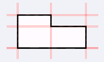
We can further trim the boundaries according to the requirements.
Note: The icon of the Construction Line will be visible under the 'Draw' section on the ribbon panel.
The construction line can be drawn in different ways, which are listed below:
- Horizontal
- Vertical
- Angle
- Bisect
- Offset
Let's discuss each type.
Horizontal Construction Line
The steps to create a horizontal construction line are listed below:- Click on the Construction Line icon, as shown in the below image:

Or
Type XL on the command line and press Enter. - Type H on the command line or command prompt and press Enter.
Or
Select Hor option displayed on the command line, as shown in the below image:

- Specify a through point on the viewport.
The horizontal construction line of infinite length will be drawn, as shown in the below image:
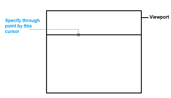
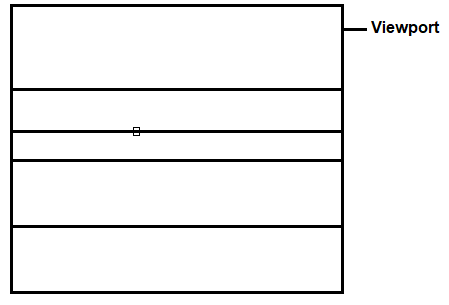
We can draw multiple horizontal lines by clicking (specifying the through point) as many times on the viewport.
It is shown in the below image:
Vertical Construction Line
The steps to create a vertical construction line are listed below:
- Click on the Construction Line icon, as shown in the below image:

Or
Type XL on the command line and press Enter. - Type V on the command line or command prompt and press Enter.
Or
Select Ver option on the command line. It is shown in the below image:

- Specify through point on the viewport.
The vertical construction line of infinite length will be drawn, as shown in the below image:
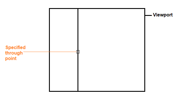
We can draw multiple vertical lines by clicking (specifying the through point) as many times on the viewport.
Angle Construction Line
The steps to create an angle construction line are listed below:
- Click on the Construction Line icon, as shown in the below image:

Or
Type XL on the command line and press Enter. - Type A on the command line or command prompt and press Enter.
Or
Select Ang option on the command line. It is shown in the below image:

- Specify the angle of XLine (Construction line). For example, 30.
Remember: The angle is measured in counter-clockwise direction in AutoCAD.
The line of infinite length will be drawn, as shown in the below image:
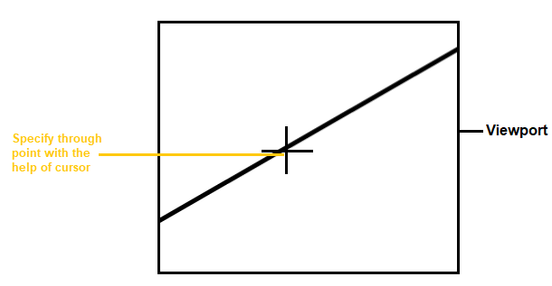
Or
Specify the first and second point on the viewport, as shown in the below image:
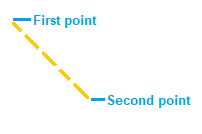
The construction line will be drawn, as shown in the below image:
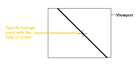
Or
Specify the reference point for the construction line. For that:
- Type R or Reference on the command line after step 1 and step 2 as given above.
- Select the reference line object.
- Specify the angle.
- Specify the through point and place the line on the desired position with the help of cursor.
We can specify any reference point according to the requirements.
Here, we have specified the reference point, as shown in the below image:
Bisect Construction Line
It creates all the lines from the specified angle vertex point or bisect point.
Let's understand by example.
The steps to create a horizontal construction line are listed below:
- Click on the Construction Line icon, as shown in the below image:

Or
Type XL on the command line and press Enter. - Type B on the command line or command prompt and press Enter.
Or
Select Bisect option on the command line. It is shown in the below image:

- Specify the angle vertex point.
- Specify angle start point, as shown in the below image:
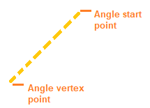
You can specify these two points according to the requirements. - Specify the angle end point. It will be the point to fix the position of the construction line.
The construction line will be drawn, as shown in the below image:
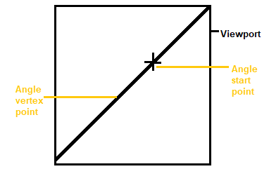
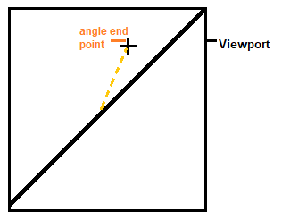
- Similarly, continue specifying the angle end point to draw multiple lines. These lines will be drawn with a fixed specified vertex point. It is shown in the below image:
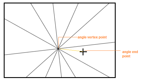
Offset Construction Line
It is used to create an offset of a specified line object.
Let's understand with an example.
The steps to create a horizontal construction line are listed below:
- Click on the Construction Line icon, as shown in the below image:

Or
Type XL on the command line and press Enter. - Type O on the command line or command prompt and press Enter.
Or
Select the Offset option on the command line. It is shown in the below image:

- Specify the offset distance. For example, 2.
- Select a line object.
- Specify the side (direction) to create an offset, as shown in the below image:
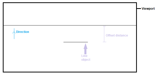
Similarly, we can use the above types of construction line in multiple ways.
How to Draw a Line With Specified Angle in Autocad
Source: https://www.javatpoint.com/autocad-construction-line
0 Response to "How to Draw a Line With Specified Angle in Autocad"
Post a Comment